Architecture
Water-Level Measurement and Control Signal Path
Architecture
The laboratory is organized as a complete measurement-and-control chain rather than as isolated PLC exercises.
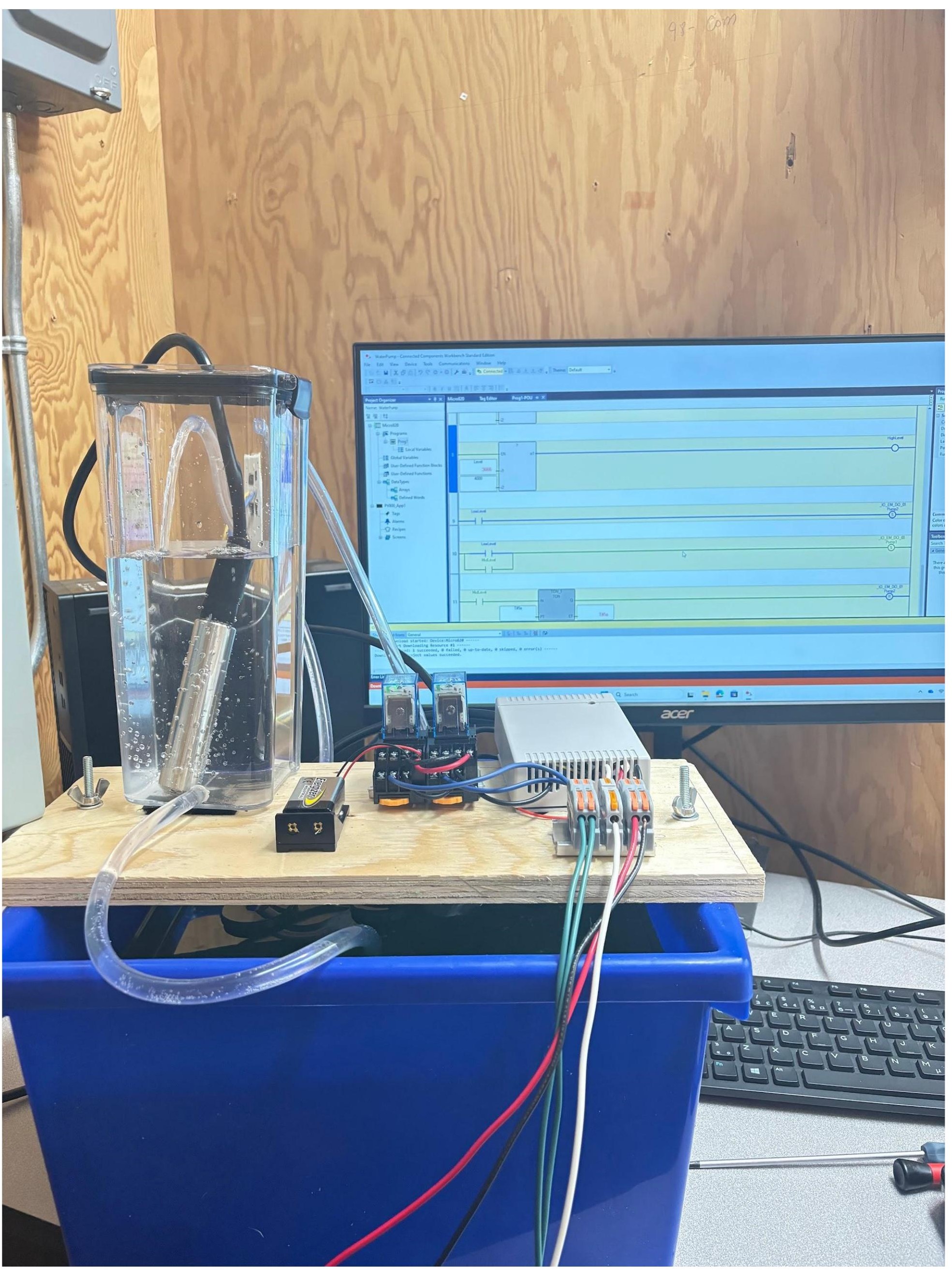
Functional Architecture
Physical Process → Measurement → Signal Adaptation → PLC Processing → Output Interface → Actuation → Physical Process
In the implemented system this becomes:
Reservoir Level → 4–20 mA Level Sensor → Signal Conditioning → Voltage Analog Input → PLC Logic → Relay → DC Pump → Reservoir
Measurement Layer
An industrial level sensor provides a continuous 4–20 mA signal proportional to water level. This gives students exposure to a standard industrial instrumentation interface rather than limiting the activity to a potentiometer or simulated value.
Signal-Conditioning Layer
The available PLC uses voltage-based analog inputs, creating a deliberate compatibility problem between the industrial sensor and controller.
The signal-conditioning stage performs two functions:
- converts the current-loop information into a voltage compatible with the PLC;
- expands the useful measurement span from the approximately 1–1.9 V produced by the small reservoir geometry to approximately 1–10 V.
This demonstrates that the physical process, sensing method, electronics, and PLC analog-to-digital conversion cannot be treated independently.
Control Layer
The PLC separates the application into input acquisition, decision logic, and output control. Conditioned analog values are interpreted through thresholds and timing logic before outputs are actuated.
Stabilization Layer
Two complementary mechanisms are used:
- Hardware filtering attenuates high-frequency electrical noise before analog-to-digital conversion.
- Software hysteresis and temporal control prevent rapid state changes and excessive pump cycling near control thresholds.
Actuation Layer
PLC outputs operate relays that switch the DC pumps. The pump action changes the physical reservoir level, completing the observable process-control loop.
Functional Verification
The laboratory is verified through system behavior rather than only through PLC status indicators. A successful implementation must demonstrate stable level measurement, predictable threshold response, and pump operation without excessive cycling.